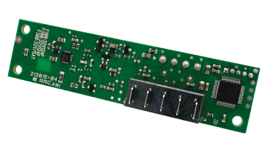
RRC-PMM20
Power Management Module for integration into all applications using RRC20xx batteries
The PMM20 enables internal charging of batteries and facilitates a seamless switch between mains and battery power, ensuring uninterrupted operation and reliable power backup in a space-saving design.
- Easy to design in, easy integration into slot design
- Plug & Play available embedded charging solution for RRC20XX standard battery packs
- Power management functionality
- Fully compliant with Smart Battery Specification
- Worldwide certified for industrial and medical applications
- Configurable
Multiple PMMs can be used in parallel inside one device to combine more batteries.
더 많은 정보를 찾고 계십니까?
Downloads RRC-PMM20
RRC-PMM20
Specification
| Power supply Input | |
|---|---|
| Input voltage range | 7.50 - 24.00V, min. battery charge voltage +1.00V |
| Total input power | 240.00W max. |
| Input current | 10.00A max. |
| Input fuse | 12A |
| Protection | Reverse polarity, short current |
| Application Output | |
|---|---|
| Output voltage range | Equal to DC input voltage if external DC power supply is present |
| Total output power | 168.00W max. in battery mode 160.00W max. in power supply mode |
| Output current | 10.00A max. |
| Output fuse | 12A |
| Power Management | |
|---|---|
| Automatic power source selection with seamless transition between external DC power supply and battery | |
| Battery Input / Output | |
|---|---|
| Battery charge voltage | Up to 17.40V |
| Battery charge current | Up to 3.60A |
| Battery charge power | Up to 40.00W |
| Battery discharge current | 10.00A max. |
| Protection | Battery short circuit, over temperature, over voltage, over current & reverse polarity |
| Standby current | 300μA |
| Environmental Condition & User Interface | |
|---|---|
| Operating Temperature | -20° to +60°C |
| Transport & Storage Temperature | -20° to +60°C |
| Relative Humidity | 5% - 95% non-condensing |
| Altitude | 5000m for operation and storage |
| User Interface | |
|---|---|
| UI via GPIO / available info | Charging: yes/no |
| SMBus commands to set | Charge current limit, input current limit |
| Battery information available | via standard SMBus |
| Battery architecture | DC input voltage | Power supply wattage @ 4.00A max input current | Power supply wattage @ 8.00A max input current |
|---|---|---|---|
1SxP | 6.00VDC | ≥30.00W | ≥60.00W |
2SxP | 12.00VDC | ≥48.00W | ≥96.00W |
3SxP | 15.00VDC | ≥64.00W | ≥128.00W |
4SxP | 19.00VDC | ≥80.00W | ≥160.00W |
| Reglatory Approvals | |
|---|---|
| International | IEC 60601-1(ed.3), IEC 60601-1(ed.3) am1 |
| Europe | CE, UKCA (EMC) |
| USA | FCC (EMC) |
| Environmental | RoHS |
| Mechanical Details | |
|---|---|
| Boards dimensions (LxWxH) | ~87mm x 22.40mm, without cables and connectors With 3 mounting holes |
| Weight | 16g |
| Battery Connector | 1x battery pack accessible via 180° mating connector for RRC20xx batteries |
| Input/Output Connector | 1x 90° / 4pin JST style header on PCBA |
| Communication Interface | 90° / 5pin JST style header on PCBA with 2xSMBus lines, GND and 2xGPIO |


